Removable Bicycle LED Light Mount
I needed a substantially brighter light for riding my bicycle at night, but the rechargeable LED lamp I already owned was designed to be worn as a headlamp.
Rather than replace the light, I designed a mechanical system that adapted it to the bicycle while preserving two important functions: adjustable aiming and easy removal for charging.
The resulting assembly was designed in SolidWorks, manufactured in PETG using FDM 3D printing, and iterated through physical testing on the bicycle.
The first functional version successfully mounted the lamp, retained its indexed angular adjustment, allowed the lamp assembly to slide off without tools, and reduced the handlebar attachment to only two fasteners.
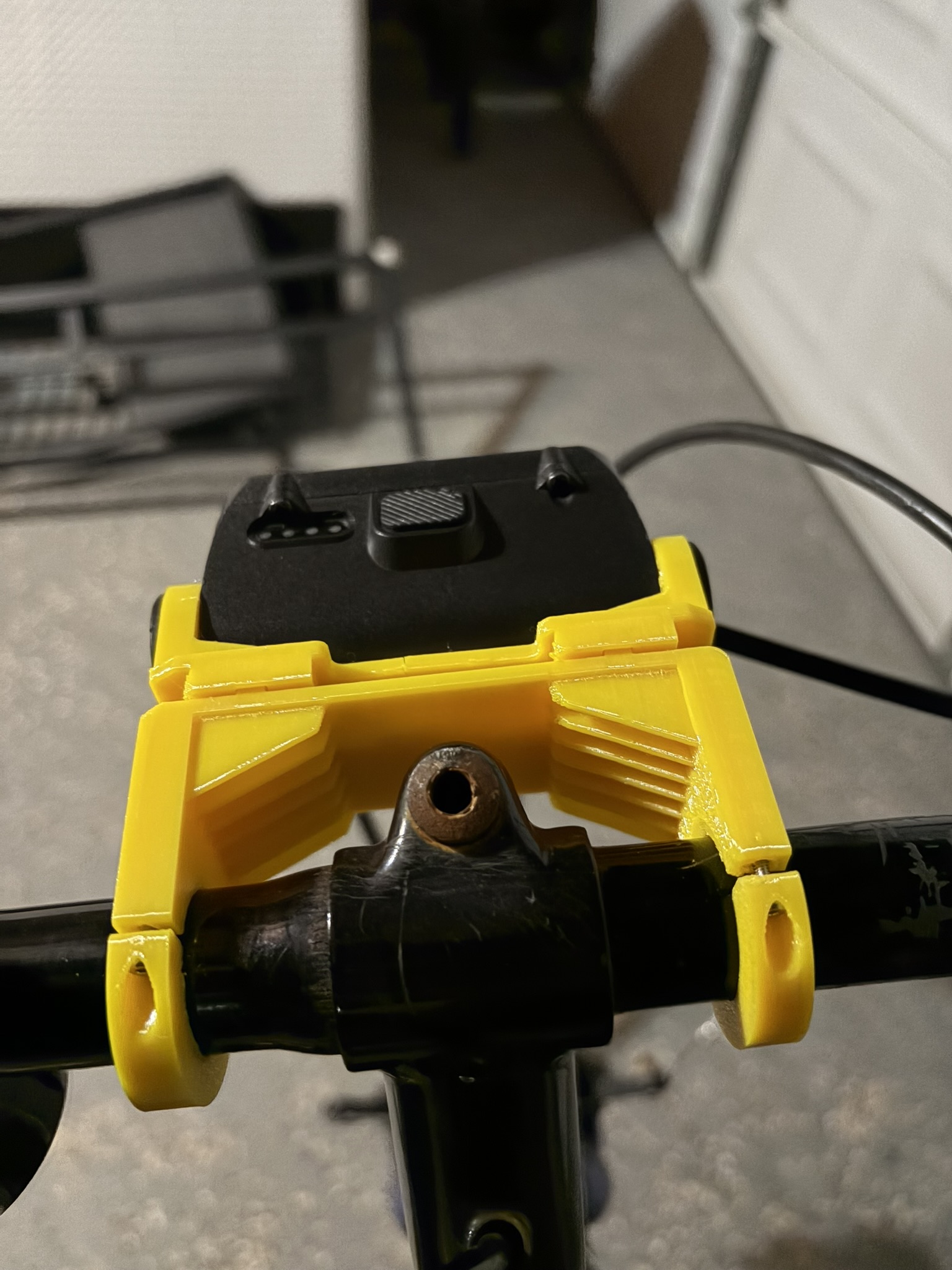

Functional V1 prototype installed on the bicycle.
Starting With the Existing Product
The original lamp already contained a powerful rechargeable LED, battery, controls, and an indexed pivot mechanism that allowed the beam angle to be adjusted.
The problem was therefore not designing another light. It was designing the mechanical interface required to turn an existing headlamp into a practical bicycle light.
My initial requirements were to:
- mount the lamp securely to the handlebar,
- retain its existing adjustable aiming mechanism,
- allow the lamp to be quickly removed for charging,
- minimize fastener count and loose hardware,
- package the design around existing bicycle components and cables,
- manufacture the prototype using FDM 3D printing, and
- create geometry that looked intentional rather than simply attaching the lamp with a basic bracket.
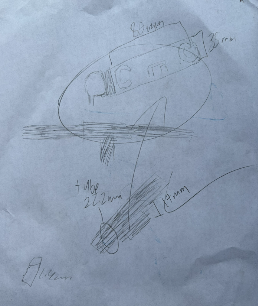
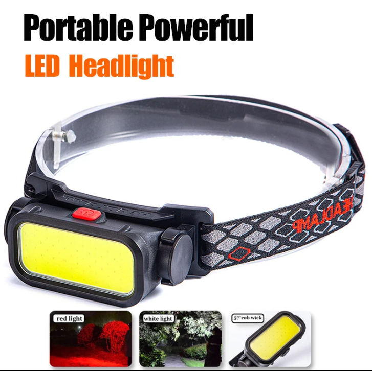
Early concept sketch and the LED lamp in its original head-mounted configuration.
The initial sketch helped establish the basic architecture before I moved into detailed CAD: a fixed bicycle interface, a removable lamp carrier, and a mechanism that reused the light’s existing pivot geometry.
Mechanical Architecture
I divided the design into two main subsystems:
- a handlebar-mounted base that remains attached to the bicycle, and
- a removable lamp carrier that holds and interfaces with the LED lamp.
This separation allowed each portion of the design to serve a distinct function.
The handlebar base provides structural support and alignment, while the lamp carrier can be removed independently whenever the light needs to be charged.
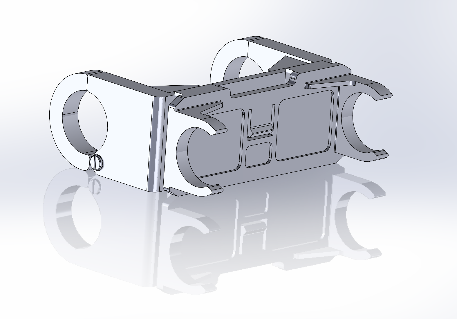
SolidWorks assembly showing the handlebar clamps, structural bridge, removable lamp carrier, and sliding interfaces.
Tool-Free Removal for Charging
Because the lamp is rechargeable, I did not want charging to require loosening fasteners or removing the entire handlebar mount.
I therefore incorporated mating T-style sliding interfaces between the fixed bicycle mount and the lamp carrier.
The printed sliding geometry was designed with approximately 0.25 mm of clearance per mating side, providing enough tolerance for FDM manufacturing while maintaining controlled alignment of the two components.
Once installed, the rails constrain the lamp carrier during normal use. When charging is required, the carrier can simply slide out of the fixed mount.
T-style sliding interface allows the lamp carrier to be removed without disturbing the handlebar clamps.
This preserved the convenience of a removable consumer product rather than turning the lamp into a permanently attached bicycle component.
Reducing Four Fasteners to Two
A straightforward split-clamp design could have used two screws on each handlebar clamp, resulting in four total fasteners.
Instead, I designed one side of each C-clamp around an integrated snap-in locating feature.
The feature constrains relative rotation and alignment between the mating clamp components while the screw on the opposite side supplies the clamping force.
This allowed each clamp to use only one screw, reducing the complete assembly from four fasteners to two.
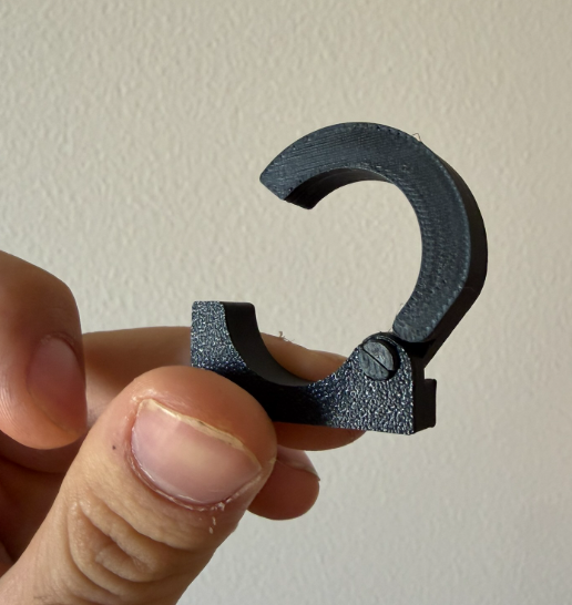
Integrated locating joint replaces one conventional fastener location on each handlebar clamp.
Iterating the Snap-Fit Geometry
The locating feature required several physical iterations.
Small dimensional changes had a large effect on whether the two pieces could:
- snap together,
- rotate into their assembled position,
- remain constrained after installation, and
- avoid excessive interference during assembly.
Retaining Indexed Angle Adjustment
The original headlamp used a compliant click mechanism to lock the lamp at discrete aiming angles.
Rather than replace that functionality with a fixed mount, I designed the lamp carrier to engage the original indexing geometry.
This required another compliant PETG feature.
The first version was too thin and susceptible to excessive bending and permanent deformation. I therefore iterated the tab by:
- increasing its cross-sectional thickness,
- increasing the section near the root where bending moment is highest,
- tapering the geometry to create a smoother transition into the surrounding structure,
- maintaining enough compliance for repeated engagement with the lamp’s detents, and
- adjusting print orientation to improve strength.
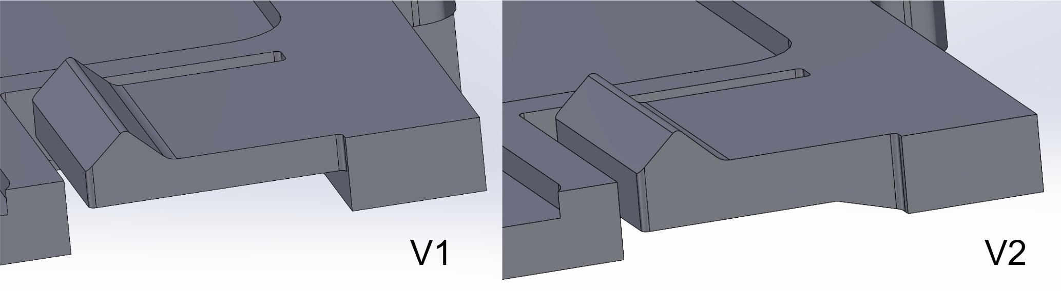
Iterations of the compliant indexing feature used to retain discrete lamp aiming angles.
Designing Around FDM Anisotropy
Because the indexing feature repeatedly bends during angle adjustment, print orientation became part of the mechanical design.
FDM components are significantly weaker when a load attempts to separate adjacent printed layers.
I therefore oriented the part so that the compliant walls were printed parallel to the layer planes, keeping the primary bending stresses within continuous printed material rather than relying on weaker interlayer adhesion.
This allowed material selection, geometry, and manufacturing orientation to work together rather than treating them as independent decisions.
PETG and Structural Design
The final prototype was printed in PETG.
PETG provided greater toughness and compliance than a more brittle PLA component while remaining straightforward to manufacture on an FDM printer.
The structural bridge incorporates ribs and gussets in several locations to increase local stiffness without simply making the entire structure solid.
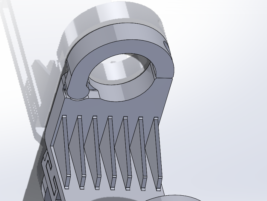
Ribs and gussets increase local stiffness while reducing the need for uniformly thick solid sections.
The rib geometry also allowed me to explore design features more representative of molded consumer components, including tapered features, filleted transitions, and locally reinforced load paths.
Heat-Set Insert Development
Reusable threaded joints were created using heat-set threaded inserts rather than printed polymer threads.
Initial testing showed that both the designed hole geometry and the installation process strongly affected insert retention.
Improperly installed inserts could pull out of the surrounding PETG rather than transferring the intended clamp load into the structure.
I adjusted the insert holes and installation technique before assembling the complete prototype.
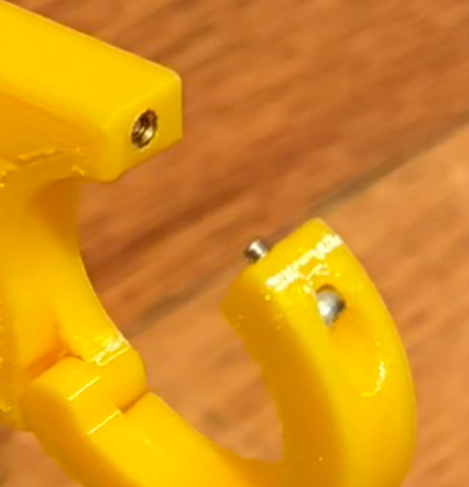
Heat-set inserts provide reusable metal threads for the two primary clamp fasteners.
Clamp Retention and Friction
The handlebar interface also required iteration.
The initial clamp geometry could be tightened onto the bar, but the assembly could still rotate when sufficient torque was applied.
Part of the issue was geometric fit, so I reduced the clamp diameter to increase preload.
However, the interface also consisted of smooth PETG against glossy painted metal, producing relatively low friction even when the fasteners were tightened.
Sanding the PETG contact surface significantly improved grip, confirming that interface friction was a major contributor to the observed slipping.
The current prototype remains stable during normal operation, although sufficient externally applied torque can still rotate the complete structure.
This is one of the primary improvements planned for the next iteration.
Functional V1 Prototype
The first complete prototype validated the core mechanical architecture.
It demonstrated that:
- the lamp could be mounted to the bicycle,
- the original indexed aiming function could be retained,
- the light could be removed without tools for charging,
- the sliding interface could repeatedly engage and disengage,
- the snap-fit locating joints could replace two conventional fasteners,
- only two screws were required to clamp the entire assembly to the bicycle, and
- the complete system could package around the actual bicycle hardware.
On-Bike Testing
The final step for V1 was testing the assembly in its actual use environment.
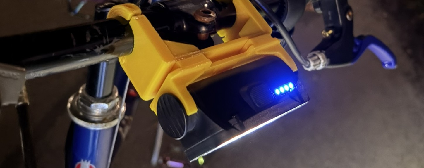
Rather than stopping at a bench-top fit check, I installed the mount on the bicycle and used the LED during night riding.
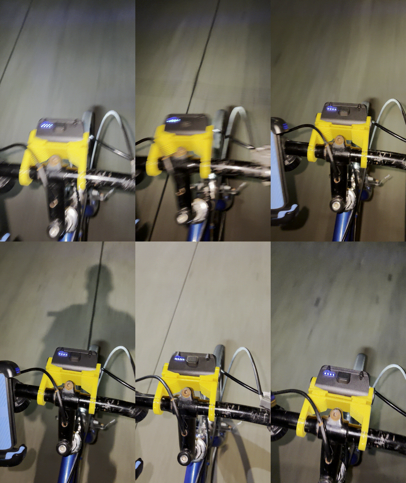
Functional testing of the V1 mount during night riding.
The prototype remained functional during use and demonstrated that the overall mounting architecture was viable.
More importantly, testing identified the specific areas that should be improved rather than requiring a complete redesign.
What I Learned
What initially appeared to be a simple mounting problem quickly became an exercise in several interacting mechanical design considerations:
- sliding-fit tolerances,
- snap-fit geometry,
- compliant mechanism design,
- FDM anisotropy,
- material selection,
- heat-set insert retention,
- clamp preload,
- friction,
- real-world packaging,
- assembly sequence, and
- user serviceability.
The project reinforced the value of physical prototyping as more than a final validation step.
Each prototype exposed assumptions that were difficult to identify from CAD alone and provided direct information for the next design iteration.
Current Status
V1 is functional and has been tested on the bicycle.
The core architecture worked successfully, so future development will focus primarily on refinement rather than replacing the concept.
The removable carrier, indexed aiming system, two-fastener clamp architecture, and integrated locating joints will all be retained.
Future Improvements
The next iteration will focus on:
- increasing friction at the handlebar interface,
- evaluating an elastomeric or TPU liner,
- further refining clamp preload and diameter,
- improving repeatability of the snap-fit interfaces,
- continuing to improve heat-set insert retention,
- evaluating long-term wear of the sliding interface,
- performing structural FEA on the complete assembly,
- identifying low-stress regions where material can be removed,
- reducing overall mass,
- and further developing the geometry around molded-part design principles.
The V1 design intentionally prioritized functionality and rapid physical validation.
Future iterations will use the information gathered from testing to produce a lighter, cleaner, and more robust version while preserving the core architecture proven by the first prototype.