Making a Magnetic Museum Exhibit Easier to Reset
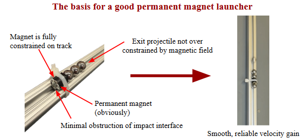
A steel ball rolls toward a permanent magnet, accelerates, and strikes it. The collision transfers momentum through the magnet and the balls touching its opposite side, launching the outermost ball down the track. Repeating this process through multiple stages increases the outgoing ball’s speed.
Our team is adapting this magnetic launcher into a hands-on exhibit for the Ann Arbor Hands-On Museum, letting children see and feel magnetic forces in action.
Launcher prototype demonstrating the magnetic acceleration and collision sequence.
The challenge is resetting it: after a launch, steel balls remain strongly attracted to the magnets. Children need a simple way to separate and reposition them for another turn.
I designed, built, and tested a lever-driven reset mechanism, owning the lever, linkage, carriage, and spring-steel plate attachment. My work focuses on making that interaction intuitive while keeping wear components easy for museum staff to replace.
Current Design: A Wheeled Reset Carriage
My latest design combines the lever mechanism with a two-level 80/20 track. The upper level supports the balls and magnets; the lower level guides the reset carriage on wheels.
I replaced the earlier sliding-shaft arrangement with rolling contact to improve carriage motion and concentrate routine wear in replaceable wheels. I also designed a friction clamp that holds the spring-steel plate without drilling through it, simplifying fabrication and replacement. I am currently building this revision.
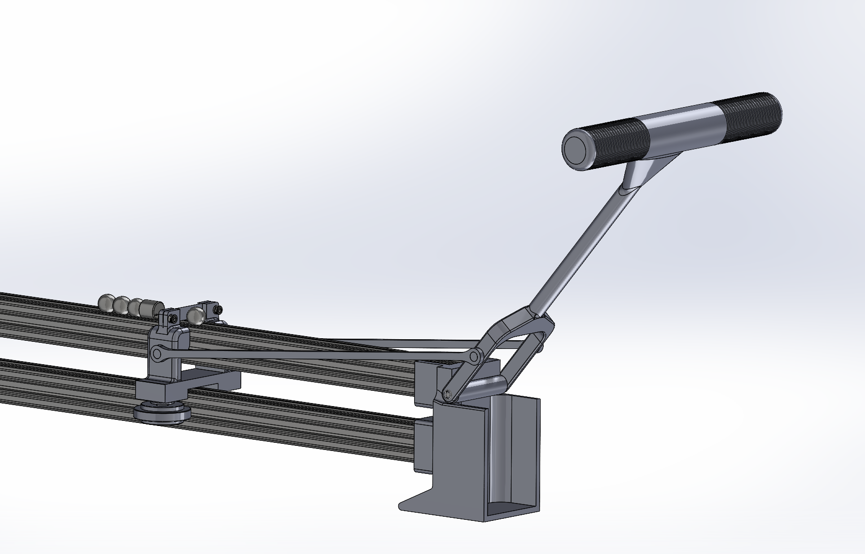
Current design: the upper track carries the launch components while the lower track guides the wheeled carriage.
Building and Testing the Lever Mechanism
I developed the lever and connecting linkage in SolidWorks to move the separator plates along the launcher. The lever provides mechanical advantage, and the connecting rods transmit handle motion to the reset carriages.
I built and bench-tested the lever-and-plate mechanism, demonstrating separation of the ball from the permanent magnet. That testing informed the carriage and plate-mounting changes in the current design.
Bench test of the lever-driven plate separation mechanism.

Earlier shaft-guided design, before the move to the wheeled carriage shown above.
Handle length affects both input force and travel. Planned museum trials will compare lever lengths to assess comfort and ease of operation for children.
One Plate, Two Functions
I developed a replaceable spring-steel plate to protect the magnet during launch and separate the ball during reset. This lets one component handle repeated impacts and provide the contact surface for the reset mechanism.
I compared shield configurations through physical testing. A shorter configuration showed the most promising balance of launch performance and durability in those tests. Early handheld separation experiments then established the concept I incorporated into the lever assembly.
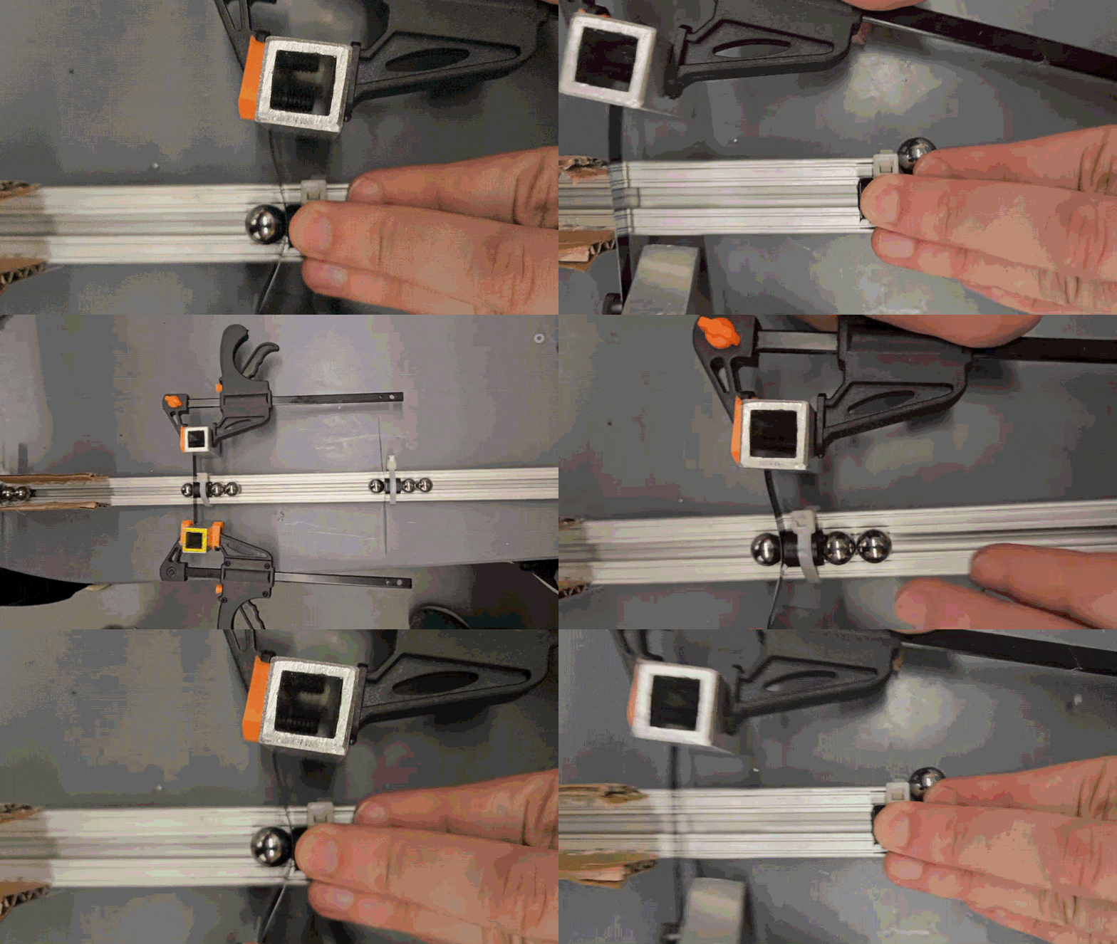
Early testing of the plate's separation function.
Earlier Iteration: Learning from the Power Screw
My first reset design used a handwheel and power screw to translate the plate carriage. We built and tested it, but the screw-driven motion made magnetic separation difficult to feel.
That feedback changed the design direction. I moved to lever actuation to give visitors a more direct sense of magnetic resistance while retaining mechanical advantage.
Launcher Development
Alongside the reset work, I helped build and test permanent-magnet launcher prototypes, investigating magnet spacing, ball spacing, and track constraints. Our team selected permanent magnets to preserve the visible launch sequence while avoiding powered controls and thermal-management requirements.